- Home
- PIC Projects
- EEPROM
12F675 Tutorial 5 : A Temperature data logger using PIC EEPROM.
EEPROM is useful for storing long term data
such as data logger information and this PIC microcontroller EEPROM project
saves the temperature from an LM35DZ IC to the PIC's internal long term data
storage area. The project follows on from the last project using the
virtually the same hardware.
It stores temperature
readings internally at regular intervals until full and after this it turns on
the LED. The LED is really just for showing that something is happening and in
a real data logger you would not use it.
Note: This project is not optimized for power
consumption so the best way to use it is powered from a power block. The
current consumed is about 13mA (LED off) 16mA (LED on at end). If you want to
use a battery use a rechargeable PP3 and do not attach the LED.
The 12F675 may not the
best PIC microcontroller to use for low power data logging and a better choice
would be the 16F88 as it can change its internal oscillator on the fly going
into slow (current saving) mode. But you could use the 12F675 with a slow
external 32kHz crystal.
At
every ADC reading the LED is flashed briefly and when you select a 500ms
reading interval you can see the readings being taken. When 64 readings are
accumulated the LED is lit permanently - showing that the data store is
full.
Note: For this chip you only get to store 64 results as you need to store an unsigned integer for every ADC result and this takes 2 bytes so 128 Bytes/2 = 64 results.
To erase the internal EEPROM hold the button and cycle the power - this flashes the led 6 times indicating erase (normal startup flashes the LED 3 times).
Solderless breadboard
The solderless breadboard and circuit diagram are nearly the same as used in the previous project so if you have already built it you don't need to do any more. Just add the blue wire, D2 and R6.
Circuit diagram
Note: The diode stops the programming voltage conflicting with the 5V power supply - reversed biased when the high programming voltage is present.
Setting GP3 low causes a reading update rate of half a second (for debug) while setting it high causes a reading update rate of approximately 30 minutes. So for the full 64 readings you get temperatures measured and stored every half hour over a 32 hour period.
Note: The measurement time is not calibrated so it won't be exactly 30 minutes.
Note: The circuit/software is not optimized for power usage so you should use a power block to give the circuit power otherwise a battery would be drained fairly quickly.

12F675 pinouts

Other views:
 |
 |
Software
Again the Soft USART (transmit only) described in Tutorial 3 is used and internal MikroC routines are used to get data from analogue input (AN0) and for reading from and writing to the internal EEPROM.
Source code files :
To get the file
software project files and c source code click here.
PIC Microcontroller Software operation
As mentioned before setting GP3 high causes the measurement interval to be approximately 30 minutes whereas holding it low causes a half second measurement interval (for debug).
Once the internal EEPROM is full up no more readings are taken and the LED is turned on permanently.
Pressing the key at any point transmits the EEPROM data to the serial port for display/use on the PC.
Software routines
The software used to gather the temperature reading is the same as the software in tutorial 4 except averaging is done in a separate function :For debug the led is flashed briefly to show a data capture.
The following sub routines are defined and their function is obvious:
printval()
erase()
eeTemp_write()
eeTemp_read()
get_reading()
flash_led_3times()
report()
finished()
The rest of the action happens in main() in an infinite loop. It gets a reading,sends it to the serial port and then stores it in EEPROM. It then flashes the LED briefly checks the key state, then checks to see if all data is gathered and then waits for a delay (the length is determined by the state of GP3 - pin 4) either 30 minutes or 0.5 seconds.
| Back | 12F675 Tutorial Index | Next |
Site Map | Terms of Use
Search:
Recent Articles
-
Arduino Hall Effect Sensor Tutorial: Detect Magnets Easily
 Arduino Hall Effect Sensor: Add magnetic sensing superpowers to your Arduino projects with an easy-to-use hall effect sensor. With full code and layout...
 -
Logic Level Converter: Easily Convert between 5V and 3V
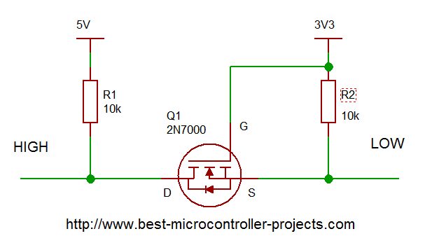 Logic Level Converter: How to create a bi-directional interface that automatically translates voltage levels using a subtle MOSFET property...
 -
Arduino Ultrasonic Sensors: A Beginner's Guide to the HC SR04
 A step-by-step guide to using Arduino ultrasonic sensors for object detection and distance measurement. Details the libraries you need, example code and circuit diagram.
 -
Arduino Humidity Sensor: A Beginners Tutorial on the DHT11 sensor
 Get started with an Arduino humidity sensor using the DHT11, which reports both humidity and temperature. Complete guide with full code for using this sensor
 -
A beginners Arduino Project to Control an LED with a Button
 This beginners guide shows you how to build a simple Arduino circuit to control an LED using a push button. Full connection details and example program included...
 -
Arduino digitalRead; A tutorial on Reliably reading Push Buttons
 In this beginner Arduino digitalRead tutorial you'll learn how to use the digitalRead function to read a button avoiding switch bounce. Full example code and explanation included
you so so so much
for all the information
you have provided in
your site it's
SUPERB and FANTASTIC."
- Ranish Pottath
the best and my favorite.
I find here many useful
projects and tips."
- Milan
bursach<at>gmail.com<
very, very easy and nice
to navigate!"
- Matt
matt_tr<at>
wolf359.cjb.net
"I am a newbie to PIC
and I wanted to say
how great your
site has been for me."
- Dave
de_scott<at>bellsouth.net
and perfect work.
congratulations."
- Suresh
integratredinfosys<at>
yahoo.com
words to define
yourweb site.
Very useful, uncovered,
honest and clear.
Thanks so much for
your time and works.
Regards."
- Anon
Comments
Have your say about what you just read! Leave me a comment in the box below.
Don’t see the comments box? Log in to your Facebook account, give Facebook consent, then return to this page and refresh it.