- Home
- Arduino Interfaces
- Spi Interface
- Home
- Arduino Hardware
- Spi Interface
SPI interface Tutorial.
The SPI Interface (Serial Peripheral Interface) bus is a high speed, 3-wire, serial communications protocol (4 if you include SSn - see below). Its primiary purpose is to reduce on-PCB wire routing by replacing the traditional parallel bus with a serial interface. (You can just about manage an 8 bit bus routing it through a several layer PCB but when you get to 16, 32 bits and more it gets far more difficult).
The connections are:
- MOSI (Master Out Slave In) [SDO].
- MISO (Master In Slave Out) [SDI].
- SCK (Slave Clock) [SCK].
- SS_n (Slave Select).
[] - denotes PIC nomenclature
Note: The last signal SS or slave select is separate from the protocol and is usually implemented as an enabling control pin from the microcontroller. It is included here for completeness.
The SPI PIC interface allows connection of peripherals using a high speed serial interface. SPI Flash Memory and SPI SRAM can easily be added to any system. Other types of device include:
- ADC.
- DAC.
- Flash.
- EEPROM.
- Accellerometers.
- LCDs.
- Temperature & Humidity sensors.
- ...and many more.
Its only other real competition is the I2C bus which is why you often see these interfaces both available on processors and microcontrollers.
The SPI interface was designed in the 1970s by Motorola, who used it in their 68000 processor, and it was quickly adopted by many other manufacturers as a defacto standard.
It is intended for transmission of data from a master device to one or more slave devices over short distances and at high speeds (MHz).
How it Works
It works by transferring data one bit at a time between two devices with the master device sending the clock signal (SCK). The clock controls the timing of the data transfer.
Data (MOSI [SDO] )is sent out of a shift register in the Master SPI device along with a clock signal (SCK) while at the same time another shift register receives data from the slave (MISO, [SDI]).
The Master is always in control and initiates data transfer using the clock signal. Slave devices are selected using a separate slave select signal that is software controlled i.e. those signals are separate from the SPI hardware module.
Note: The number of bits is not defined by the protocol so you are not limited to using only 8 - it can be any number of bits. This is useful when daisy chaining SPI slaves as you need to set the number of bits to the sum of all the bits required by each device.
Note: SPI defines a single master system.
The alternative protocol, IIC, allows multiple bus master operation.
SPI interface Clock Definition
The SPI clock is not defined at all - meaning that different slave devices can assume different clock operation; One slave may require an idle clock that is high, while another may require an idle state of low. Others will react to the rising edge while others react to the falling edge!
The SPI interface protocl copes with this by letting you program these details to the SPI hardware module.
The following image shows the PIC interface for SPI (all SPI hardware modules in other microcontrollers will allow the same operation just using different registers).
SPI Interface PIC signals (extract from PIC datasheet DS39582B)

It is up to you to set the correct clock for you device when it is activated by a slave select signal (or in the case of a single slave it is always selected so there will be no slave select signal).
Arduino SPI Connection
The following diagram shows the interface to the SPI connections which also happens to be the programming connector (ICSP), on the Arduino board, that allows direct programming of the ATmega328p.
|
1 - MISO |
2 - Vcc |
|
3 - SCK |
4 - MOSI |
|
5 - Reset |
6 - GND |
Location of the SPI connector on Arduino Uno R3
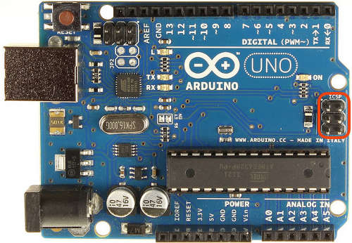
Photo Credit : kenming_wang (mod shows ICSP - modified with rectangle red highlite)
Different SPI Interface operational Modes
There are three ways of using the SPI interface
- Single Master - Single Slave.
- Single Master - Multiple Slaves - Chip selected.
- Single Master - Multiple Slaves - Dasiy chained.
Single Master - Single Slave.
Here is the setup for a single SPI device connection:
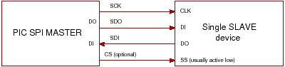
Note: The chip select signal SS is optional for a single device system as you will normally tie the SS input at the slave low (if the other lines are dedicated to SPI use).
SIP Interface : Using chip selects
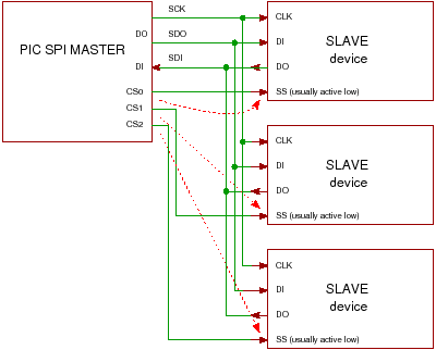
With this scheme you control each slave device using
its chip select line (usually active low- red arrows show control
lines). When disabled the
Data output from the
slave goes into a high impedance state so it does not interfere with
the
currently selected slave and the slave's data input is ignored (check
datasheet).
The advantage of this scheme is that you can consider (control) each device
separately when you compare it with the daisy chain method - allowing connection of SPI devices that require different clock schemes.
If you have SPI slaves that operate using different clocks (edges/idle states) you can re-programme the master SPI hardware module before enabling a specific CS so each slave has the correct signals sent to it.
If you use the Daisy chain method then you need to make sure all the chips use the same clock edge and idle clock state.
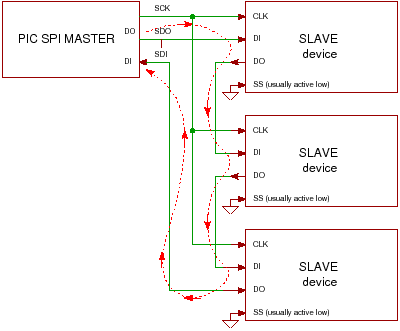
SPI Interface : Daisy chaining
With this scheme all data sent by the master is shifted into all devices and all data sent from each device is shifted out to the next (shown by red dotted arrow). For this scheme to work you have to make sure that each slave uses the clock in the same way and you have to get the right number of bits, so there is more work to do in software.
Note: The advantage of the Daisy-Chain method is that you save a chip select signal for each slave SPI device.
More information on Wikipedia.
SPI Interface Daisy Chain
SPI Daisy Chain Example
Use several HC595 chips, daisy-chain linked, giving an easy increase in the number of outputs available without using many microcontroller pins.
The limits of operation are the speed of HC, the speed of the SPI output. Also design consideration e.g. If driving a set of LEDs that must be updated every 20ms.
Parallel Versus Serial SPI
The trade off between using a parallel interface and the SPI interface is speed e.g. if you read a parallel 12bit ADC at 200ksps then you could read the device at a 200kHz rate but if you want to get the same data rate using SPI then you need a serial speed of 200kHz x 12 = 2.4MHz. So the actual trade off is speed and the consequential noise introduced into the circuit.
Summary
The SPI interface defines a very popular protocol that works at high speed. The main problem is that slave devices are not bound by any particular clocking scheme so they may operate differently to each other and that can make controlling them difficult i.e. the clock idle and edge must be set correctly for each device.
Advantages:
- High speed.
- Exremely simple interface that is easy to replicate in software.
Disadvantages:
- Slave chips are free to adopt any clocking scheme they require.
Site Map | Terms of Use
Comments
Have your say about what you just read! Leave me a comment in the box below.
Don’t see the comments box? Log in to your Facebook account, give Facebook consent, then return to this page and refresh it.
Recent Articles
-
Arduino IR Remote: A Beginners Project for Infrared Control
May 01, 24 11:17 AM
 Introducing Arduino IR remote control [Beginners Guide]. How to build a circuit to receive and transmit IR codes through a hands-on project [full code included].
 -
Adding Arduino RFID reader Scanning to Your Projects
Apr 29, 24 12:40 PM
 This beginners tutorial gives you a complete step-by-step guide for interfacing an Arduino Uno with the MFRC522 RFID reader module. There is one problem with most circuits out there...
 -
Arduino Hall Effect Sensor Tutorial: Detect Magnets Easily
Apr 22, 24 01:39 PM
 Arduino Hall Effect Sensor: Add magnetic sensing superpowers to your Arduino projects with an easy-to-use hall effect sensor. With full code and layout...
 -
Logic Level Converter: Easily Convert between 5V and 3V
Apr 19, 24 09:35 AM
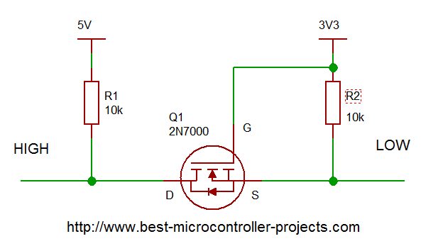 Logic Level Converter: How to create a bi-directional interface that automatically translates voltage levels using a subtle MOSFET property...
 -
Arduino Ultrasonic Sensors: A Beginner's Guide to the HC SR04
Apr 17, 24 04:21 PM
 A step-by-step guide to using Arduino ultrasonic sensors for object detection and distance measurement. Details the libraries you need, example code and circuit diagram.
 -
Arduino Humidity Sensor: A Beginners Tutorial on the DHT11 sensor
Apr 17, 24 03:05 AM
 Get started with an Arduino humidity sensor using the DHT11, which reports both humidity and temperature. Complete guide with full code for using this sensor
Comments
Have your say about what you just read! Leave me a comment in the box below.
Don’t see the comments box? Log in to your Facebook account, give Facebook consent, then return to this page and refresh it.