ATtiny85: A Power Packed
Arduino in a Tiny 8 Pin Chip. It is the smallest Arduino Chip! FOUR
features you missed! Find out How Good It is, and how you can Easily program
it over USB with no USB Chip!
The ATtiny85 device is well... physically tiny!
It is an extremely popular Arduino Chip.
You can even program it over USB (with special bootloader code).
It has 8kBytes of Flash (standalone) 6kBytes with USB capable interface.
Yes, it has less Flash and Less SRAM but it fits into an 8 pin
package. For physically small projects this is a big deal but the
question is:
How useful is it?
In fact, you can do a lot with the Flash memory size, and unless you
are writing something really complicated (or with a lot of strings
message data) then 8k/6kBytes is still very useful.
You might think that it is far inferior to the Arduino Uno with the
ATmega328P having only 8 pins (and you can use only 6 as one
is VCC and one is GND)! but it has a very respectable set of internal
peripherals and it even has a few items that are not available in a the
ATmega328P (Arduino Uno/Nano):
Internal Peripherals
Two 8 bit timers.
A 10 bit ADC.
PWM generators.
An Analog comparator.
USART - Universal Serial Interface for SPI or I2C (two wire interface).
Features not found in the ATmega328P:
An internal Clock to 16.5MHz - so you don't need an external crystal.
Two fully differential ADC inputs.
Programmable gain amplifier for the ADC x1, x20.
32MHz and 64MHz programmable internal oscillator for Timer1 clock.
Features missing from the ATtiny85
Asynchronous serial module for RS232 Serial interface - There is
no internal serial port hardware module. You can still use serial
communication but it is made in
software and that actually works just fine.
A 16 bit timer. - not a big problem (you can add an incrementing variable for longer time count in the interrupt routine).
That is to use a DigiSpark breakout board with a pre
programmed ATtiny85 programmed with a bootloader i.e. just the same as a
"normal" Arduino Uno. The bootloader allows USB communication without USB hardware!
Digispark ATtiny85 Development Board Closeup
The top 8-pin chip is the ATtiny85. The board includes a 5V regulator
(middle 7805) two LEDs - green/white SMD - (bottom left [PWR (5) - just above the 5V pin] & left of pin P2 [MISO,PB1])
and a USB micro connector (left side) as well as breakout connector pins.
The disadvantage of using the Digispark is that the Flash space is
reduced to 6kBytes because of the USB software. This sounds bad but is quite a useful amount of
memory. The advantage is that you
can use the Arduino IDE in nearly the same way as programming an Uno.
It
is just more convenient than programming the raw chip using an ISP
programmer - however if you run out of memory then you will need to do
that!
Although it has less memory than an Arduino Uno, you might want to use
this board because its small size: 24.3mm x
18.4mm. Compare this to an Arduino Uno 53mm x 70mm (75mm with USB
connector sticking out).
An alternative is the Arduino Nano that has
about the same width but twice the length. The Nano uses the ATmega328P - the same microcontroller as the Arduino Uno.
Here are more useful comparison pictures.
So, if you need to reduce space, you can see the advantage!
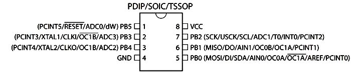
Arduino Pin 0 (PB0) : I2C SDA, PWM
Arduino Pin 1 (PB1) : PWM, (LED)
Arduino
Pin 2 (PB2) : Analog Input, I2C SCK, INT0
Arduino
Pin 3 (PB3) : Analog Input, (USB-)[this is correct buzzed out]
Arduino
Pin 4 (PB4) : Analog Input, (USB+)[this is correct buzzed out], PWM
Arduino
Pin 5 (PB5) : Analog Input, RESETn
All of the above pins can be configured as digital I/O as well.
Note: Two versions of the board exist, differentiated by the LED connection.
Originally the LED was connected to PB0 which stopped I2C being
used. The recommendation was to cut the track to the LED (to PB0). You
are likely to have a newer version with LED connected to PB1.
ATtiny85 Low Power Operation
If you are looking to make a low power battery design
then the ATtiny is a good choice. However you may want to use a raw
chip for this as you will need to program it using an ISP programmer
which gives you more control of the clock in use and consequent power
savings.
Also remember that the breakout board is not designed for low power
operation. You would need to disconnect the 7085 and LEDs as their
quiescent current is wasteful.
There is also the 1k5 resistor to Vcc that is attached to PB3 that is
for the USB id information - it will draw current if you pull it down.
Conclusions
The Digispark is convenient, allowing a USB connection that is
entirely created in software.
The downside is that you lose 2k Flash.
The up side is that you can easily program an ultra small board using
the standard Arduino IDE.
Ultimately if your program fits within 6k, then the Digispark is ideal.
If you run out of room or want very low power then program the raw Attiny85.
Note: You can use the raw ATtiny85, and program it using another Arduino
e.g. Arduino Uno - it is very possible. You can find a complete walk
through here:
Arduino Float to String: Is there a simple function that does this for you? What is the one thing you must do to ensure your program is reliable?: Find out here.


Comments
Have your say about what you just read! Leave me a comment in the box below.
Don’t see the comments box? Log in to your Facebook account, give Facebook consent, then return to this page and refresh it.