How to Setup the ESP8266 Arduino IDE with the NodeMCU V3 (ESP8266 ESP12e)
The easy way to use the ESP8266 is with the Arduino IDE and this
ESP8266 Arduino tutorial shows you how to install drivers into the
Arduino IDE to program the ESP8266. It then shows you an example sketch
using wifi.
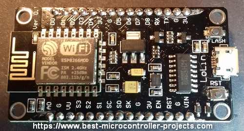
The Lolin nodeMCU V3 breakout
board is an ESP-12E style ESP8266 breakout board which makes it very
easy to use an ESP8266 device - you just plug it into a micro USB
connector and its ready.
Lolin nodeMCU V3 Board
The board includes its own 3V3 power supply regulator, a reset button, a Flash button and a
USB-to-serial chip (CH340G on mine). You can just plug it into a USB
port (micro USB connector) and start using it.
When you follow the instructions
below, you can program the Lolin NodeMCU as if it were any other Arduino
device. This is convenient since it uses the same familiar Arduino IDE
programming environment.
Note: Just so you don't get confused: Lolin is a manufacturer name - I
originally thought it meant some kind of extended range radio (similar
to a Lora device).
Warning: The Lolin nodeMCU V3
comes with the LUA scripting language flashed into it. Using the ESP8266
Arduino IDE as described below will overwrite the contents of the ESP8266. To get
LUA back you can re-flash the firmware.
(LUA is interactive scripting language - requiring no compilation,
working through a serial interface - but you need to learn another
language).
Starting the nodeMCU
When you power up the nodeMCU for the first time you will see this
message - when you connect a serial terminal on the PC - such as Tera Term
- at 9600, 8 bits, 1 stop bit, no parity (8 1 N):
This is a LUA interface which is an interactive script system - you can
type
commands directly at the prompt to get the ESP8266 to perform. However
the rest of this page shows you how to use the Arduino programming
environment to program the board in C/C++ as you would with any other
Arduino board.
If you continue past this point and Flash the Arduino sketch then
the LUA environment will be overwritten. If you want to use LUA again
you will need to re-flash the firmware.
ESP8266 Arduino Tutorial
Install USB To Serial Drivers
The first step in setting up the ESP8266 Arduino IDE is to plug in
the NODEMCU and check the Windows device Manager for an entry in the
Ports section.
If you don't see the NodeMCU showing up as shown below then you will
need to install drivers. The other possibility is that the NodeMCU is
using too much power - I found it would not work from a powered hub but
only from direct connection to the PC USB port. It needs 400mA!
External Power Source
Note: You can add an external power source to the Vin connection on
the board with voltage >5V. Also connect ground labelled 'G' to complete the circuit.
Warning: The AMS1117 absolute maximum input voltage is 15V - do not go above this i.e. do not supply a voltage to 'Vin' above 15V.
ESP8266 Arduino IDE Boards Manager
To setup the board use the board manager:
Add the following text to the "Additional Boards Manager URLs":
This will allow NODEMCU boards to appear in the main menu alongside boards such as the Arduino Uno.
Now Install the nodeMCU Boards
Start the Boards manager dialogue. Click Boards Manager...
Search for and install the "esp8266 by ESP8266 community" Entry.
Now select the nodeMCU 1.0 (ESP-12E Module) entry - this is the base
type for nodeMCU. nodeMCU is actually the firmware running on an ESP8266
ESP-12E.
Now check that you have similar information to the following - especially these:
Board "nodeMCU 1.0 (ESP-12E Module)"
Upload speed "115200baud"
CPU frequency "80MHz"
Flash Size "1M (3M SPIFFS)"
Warning: I originally set the Flash Size to 4M no SPIFF -
only the WiFi scanner example below worked - The SPIFFS is a virtual
file system that allows programs to occupy a space separate to the wifi
operational part - its like having a virtual SD card so make sure you
use the setting above (or at least allow some SPIFFS room).
ESP8266 Arduino Example Sketch
Use the ESP8266 Arduino IDE to load the following sketch - just
copy to white area of the IDE and hit the upload button. This shows you a
quick example of the ESP8266 Arduino WiFi capability.
#include "ESP8266WiFi.h"
voidsetup(){
Serial.begin(115200);
// Set WiFi to station mode and disconnect from an AP if it was previously connected
WiFi.mode(WIFI_STA);
WiFi.disconnect();
delay(100);
Serial.println("Setup done");
}
voidloop(){
Serial.println("scan start");
// WiFi.scanNetworks will return the number of networks found
intn=WiFi.scanNetworks();
Serial.println("scan done");
if(n==0){
Serial.println("no networks found");
}else{
Serial.print(n);
Serial.println(" networks found");
for(inti=0;i<n;++i){
// Print SSID and RSSI for each network found
Serial.print(i+1);
Serial.print(": ");
Serial.print(WiFi.SSID(i));
Serial.print(" (");
Serial.print(WiFi.RSSI(i));
Serial.print(")");
Serial.println((WiFi.encryptionType(i)==ENC_TYPE_NONE)?" ":"*");
delay(10);
}
}
Serial.println("");
// Wait a bit before scanning again
delay(5000);
}
ESP8266 Arduino Example Output
Here's the typical output from the sketch using the serial monitor.
A lot of code depends on libraries that you need to install before the code will compile.
Old IDE up to 1.8.19
For the older IDEs just use the Menu:
Menu > Tools > Manage Libraries
... Now wait for all the library descriptions to load!
... then type in the required library - in this case ESPAsyncTCP and you'll see:
In this case the ESPAsyncTCP library is already installed. It it were not you would see an 'Install' button to do the job.
New IDE 2.x.x onwards
The new IDE has a sidebar that you can get to libraries more easily
so you don't have to wait for the library manager to load all the
library descriptions before you can get to the one you want.
The screenshots below show the process of installing libraries for
the newer IDE. You can access this library using the menu (same as
before):
Menu > Tools > Manage Libraries
or
Click the Icon that shows books on a shelf (see image below)
You search for the required library in the top box (in this case the fauxmo library) and hit 'install'.
Conclusion
This ESP8266 Arduino IDE tutorial shows you how to flash an esp8266
with the Arduino IDE and install libraries, making it easy to create C/C++ based programs
programmed into the ESP8266.
If you want to go back to LUA there's a link to full instructions for
that on this page. One reason you might want to use LUA is that it is a
scripted language and does not require the entire Flash memory to be
programmed on each code udate so LUA is far faster to update.
Unlock the secrets of Arduino scrolling displays! This beginner-friendly guide shows you how to create real-time, dynamic graphics using an SSD1306 OLED, perfect for tracking sensor data and building…


Comments
Have your say about what you just read! Leave me a comment in the box below.
Don’t see the comments box? Log in to your Facebook account, give Facebook consent, then return to this page and refresh it.