How RS232 works : RS232 defines a protocol that details how a stream of data bits is
sequentially transmitted onto a wire i.e. a bit stream. The order and
meaning of each bit is defined by the protocol. The simple explanation
below is sufficient to understand RS232 - no need to read a big manual!
RS232 is a serial information transfer protocol standard
that defines both the protocol (method of transmission of data) and the
physical hardware to do it. This document describes how it works at the
physical level so you will know what signals you can expect to see at the
microcontroller pins.
What is RS232?
Fundamentally it is a method of transferring data across a single wire (you
need two wires to get data back since each wire transfers data in one direction
only):
It is a method (or protocol - an agreed standard) that defines how to
transfer data between two devices using a few wires. It uses a serial
transmission method where bytes of data are output one bit at a time onto a
single wire.
Data is only transmitted in one direction
for each wire so for bi-directional communication (two directions) you
need two wires. So this is not a multi
drop lan communication system such as RS485 but a point-to-point protocol.
These two along with a ground reference (total: three wires) make up the
minimum configuration that you can get away with.
Note: For more reliable communication over
long distances you may need to use other connections defined in the RS232
standard such as DTR DCT etc. handshake signals etc.
More formally RS232 is an asynchronous communication protocol that lets you
transfer data between electronic devices.
Basically it can transfer a single byte of data over a serial cable having
between 3 to 22 signals and running at speeds from 100 to 20k baud. Common
baud rates used are 2.4k, 9.6k, 19.2k, The cable length can be up to 50ft.
Higher baud rates are used but not covered by the standard they still work
though e.g. 38400,57600 Baud (bits/s).
To transfer a block of data individual bytes are transmitted one after
another.
Introduction
This section describes how RS232 works in general without describing
handshake methods - only the simplest system is described - this it the
most
useful and the most likely to work!.
Handshake signals need extra level translation hardware (an RS232
chip with more I/O) and although simple are not typically required for
PC to development board operation. You may need them for systems that
are controlling multiple devices where you may need to temporarily stop
data from a unit. There is a section on handshake signals later in this document.
Data is transmitted serially in one direction over a pair of wires. Data
going out is labeled Tx (indicating transmission) while data coming in is
labelled Rx (indicating reception). To create a two way communication system a
minimum of three wires are needed Tx, Rx and GND (ground). Crossing over Tx
& Rx between the two systems lets each unit talk to the opposite one.
Note: Each signal (TX and RX) requires a level translator since high
voltages are used for transmitting the data onto the wires (typically
output from ±5V to ±25V).
Each byte can be transmitted at any time (as long as the previous byte has
been transmitted). The transmitted byte is not synchronized to the receiver -
it is an asynchronous protocol i.e. there is no clock signal. For this reason
software at each end of the communication link must be set up exactly the same
so that each serial decoder chip can decode the serial data stream.
Note: The signal level inversion (logic 1
is -12V and logic 0 is +12V).
Baud Rate
How RS232 works in the relationship between baud rate and signal
frequency.
The baud rate is simply the transmission speed measured in bits per second.
It defines the frequency of each bit period.
For a baud rate of 2400 (2400 bps) the frequency is 2400Hz and the bit
period is 1/2400 or 416.6us. This is the information that a receiver uses to
recover the bits from the data stream.
How RS232 Works: Voltage
levels
Transmitter Voltage Levels
To make it work over long cables high voltages are sent from each
transmitter since due to cable resistance the voltage reduces the further the
signal has to travel. The output voltage specification is from +5V to +25V
(transmitting a logical zero) and -5V to -25V (transmitting a logical one).
Note: all signals in the cable have to generate the same voltage levels e.g.
DTR, DSR, RTS, CTS. So you need a lot of level translator chips for a full
interface but for very short distances you only need TX and RX and ground.
The maximum voltage of ±25V does not have to be used and a common
voltage in use is ±12V (output by MAX232 transceiver chip).
A mark (logical one) is sent as -12V and a space (logical zero) is sent as
+12V i.e. the logic sense is inverted.
Note: The fact that high voltages exist at the serial port allows
powering devices that you would not normally expect to find on it. But they
must draw very little current.
Receiver Voltage Levels
At the receiver the input the minimum voltage levels are defined as ±3V i.e. to receive
a logic zero the voltage must be greater than 3V and to receive a logic one the
voltage must be smaller than -3V. This allows for losses as the signal travels
down the cable and provides noise immunity i.e. any spurious noise up to a
level of ±3V can be tolerated without it having any effect on the receiver.
How RS2332 Works: The Bits
How RS232 works: The
RS232 Start Bit
The protocol is described as asynchronous as there is no clock transmitted
at all. Instead a different method of clock recovery is used.
At the beginning of each transmission a start bit is transmitted indicating
to the receiver that a byte of data is about to follow. Since the idle state of
the RS232 lines is low (-12V) to signal a start condition the line is set high
(+12V) for 1 bit period. This means a transition on the line is always
generated so that a receiver knows when the 1st edge of the data burst
occurs.
The start bit lets the receiver synchronize to the data bits since it can
see the rising edge of the signal on the line. What this means is that the
receiver can create its own sample clock at the middle of each bit - to decide if the bit is actually a data zero or data one.
Once the start bit is found the receiver knows where the following
bits will be
as it is given the sample period (derived from the baud rate) as part of
the
initialization process. This is why you must set the same settings in
both the receiver and the transmitter hardware i.e. baud rate, number of
stop bits, number of data bits, and parity bit (on or off). If you
don't then usually nothing will happen - or you will see rubbish
characters at the receiver.
How RS232 works: The Data
bits
Data bits follow the start bit. There will usually be seven or eight data
bits with the lsb transmitted first. The reason you can choose between seven or
eight is that ASCII is made up of the alphabet within the first seven bits (as
well as the control characters). The eighth bit extends the character set for
graphical symbols.
If you only want to transmit text then you only need 7 bits. This saves a
bit and increases transmission speed when transmitting large blocks of data.
Other data bit sizes are 5, 6, 8, and 9 bits. However bit length is usually
set to 8 bits - this is very commonly used.
TIP: Since most modules are capable of handling nine bits you
could define a use for the ninth bit such as indicating that the data packet
defines a command. But of course you have to adjust your receiver software to
process that information.
Note: If you use RS232 to transmit raw data (binary data) then you will
need 8 data bits.
How RS232 works: The Parity Bit
The RS232 parity bit is a crude error detection mechanism.
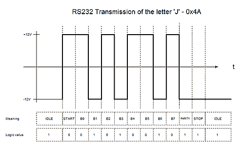
You can use either odd parity or even parity or none at all (in the diagram
above a parity bit is included (between the last data bit and the stop bit -
Here the parity is indicated as a '1' meaning that there are an odd number of
databits. So the parity in use is odd-parity. The diagram below (commonly used
in microcontroller work) does not use a parity bit.
It simply evaluates all the data bits and for odd parity returns a logic one
if there is an odd number of data bits that are set. For even parity an even
number of data bits that are set, sets the parity bit.
At the receiver the parity bit is used to tell if an error occurred during
transmission. You can use this in the receiver software by reading a flag in
the UART module.
The problem with error detection using the parity bit is that if two bits
are in error then the parity check fails. This is because each error cancels
the effect of the other (in terms of the parity calculation). Any even number
of errors causes a failure in error detection.
It won't be a problem on a bench top based system (that has no critical data
transfer). Over a short cable e.g. 6ft you probably won't see any errors
anyway. Normally I use no parity and there is no problem at all.
For systems running over a long distance or in a noisy environment a better
system should be used e.g. Adding a cyclic redundancy check to the data stream
before and after it is sent over the RS232. CRCs let you check for and correct
quite a few errors without re transmitting the data.
How RS232 works: The Stop
bit
The RS232 stop bit merely gives a period of time before the
next start bit can be transmitted. It is the opposite sense to the start bit
and because of this allows the start bit to be seen i.e. a stop bit followed by
a start bit always gives a rising edge signal for detection by the receiver.
If there was no stop bit then the last bit in the data stream would be the
parity bit (or data bit if parity is not active). This would change depending
on the data sent so if it had the same sense as the start bit then the start
bit could not be seen!
The stop bit can be set choosing from 1, 1.5, or 2 bit periods.
At very high baud rates the period from stop bit to start bit
(assuming data is being sent continuously) will be very small e.g. for a
baud rate of 115200 baud the timeing to one bit is 1/115200 = 8.26us so
by using 2 bit periods you will increase the time to 16.5us. This can
allow the receiver to detect the start bit more easily since if there is
capacitance on the line the waveforms will exhibit a CR rise fall time.
Extending the time period allows more capacitive loading. However it
also depends on the receiver hardware used.
Typical Settings
Typical settings for use on the desktop e.g. between a microcontroller and a
terminal emulator program such as "Tera Term":
How RS232 works : Typical Baud rate
settings.
Baud
9600
Data bits
8
Parity
None
Stop bits
1
Flow Control
None
This can also be compactly written as:
9600 8N1
Hardware Connections 3 (Rx,Tx,GND) - Rx and Tx crossed over.
"Flow control" in the above list is referring to a hardware flow control
signalling method that uses the signals DTR/DSR and RTS/CTS. See here for more on that.
RS232 Details
How RS232 Works: Signal Levels
At some point you may want to make a software UART perhaps to save code
space in your current design (maybe you don't need the receive part - as you
are just outputting variables) or to use a spare pin.
Note: you can find receive and transmit
software USART code in the 12F675 Tutorial
pages.
To create it you need the actual signal diagrams that you see at the
microcontroller pin (strangely these are hard to find on the web).
The following diagram shows the timed 0V and 5V bit stream at the output pin
of the microcontroller. The lower diagram shows the translated signal levels at
the RS232 output drivers which are transmitted over the serial cable.
These higher levels are are generated by sending the 0-5V logic levels to a
transceiver chip e.g. MAX232 which has a diode/capacitor boost conveter built
in that boosts the signal levels to the required RS232 voltage
of ±12 volts. Note how the -12V level corresponds to a logical '1' and +12V
level corresponds to a logical '0'.
Note: The output voltage level can be from ±5 to ±25V. For
longer distances a higher voltage is useful to offset the loss as the signal
travels down the cable but for practical use chips generate lower voltages such
as ±12.
How RS232 works when transmitting a
character
The lower waveform in the bove diagram above shows the RS232
signal that you would see using an oscilloscope on the output drive of
a translator chip such as the MAX232. Note that the RS232 idle
voltage is -12V,
RS232 Clock
The above diagram also shows the RS232 timing
diagram where each bit period is 1/frequency so for a
baud rate of 9600 bps (bits per second) the period of each bit is 1/9600 or
104.166us this is effectively the RS232 clock period required for the specific
baud rate in use.
RS232 Waveform
In the diagram above the lower waveform shows the RS232 voltage
signal that you can expect to see at the output of the RS232 TX pin
(also the same levels on the RX pin) on an oscilloscope. In some chips the
maximum signal level may not be ±12V - the max and min voltage could be
smaller (as there will not be a large voltage drop over short distances). For
long distances these should be ±12V - at the end of a long cable the voltage
will drop down across the resistance of the cable but must be more than ±3V at
the other end.
The cable capacitance will also slow the rising and falling edges - rounding
them off.
How RS232 Works: Handshake Signals
Handshake signals are simply a method of stopping data flowing. If
some part of the system is busy it may not be able to accept more data
and rather than losing it signals are used at each end of the link to
tell the other end to stop transmitting data. There are two types used
in RS232: hardware handshake and software handshake.
Hardware handshake
DTR - Data Terminal Ready.
DSR - Data Set Ready.
RTS - Request To send.
CTS - Clear To Send.
If you use these signals then they must all be transmitted at the
RS232 levels i.e. ±25V (or whatever voltage is generated by the
translator chip e.g. ±12V i.e. the same as the TX output so you need
an RS232 chip with more level translators to both transmit and receive
the signals.
Remember that the protocol was based on a modem (the DCE or Data
Communication Equipment) sitting on a desk and an attached (via RS232)
to the PC (the DTE or Data Terminal Equipment) - the controller. There's
even a ring indicator (RI) that signals when the telephone was ringing,
wired directly to the telephone line, which would allow automatic modem
detection of an incoming data stream.
Each signal is not orthogonal meaning that there is not an equivalent
signal going back the other way. This part of the protocol grew over
time so there are different uses of these signals but in general the
following is used:
To stop data coming from the PC i.e. to stop overwhelming the modem with data:
RTS (PC) to modem.
CTS (modem) to PC.
The PC asserts RTS to indicate that it wants to transmit data to the modem.
The modem asserts CTS to receive data from the PC.
To stop data coming from the modem i.e to stop overwhelming the PC with data:
.
DTR (PC) to modem.
DSR (modem) to PC.
The modem asserts DSR to indicate that it wants to transmit data to the PC.
The PC asserts DTR to receive data from the modem.
Software Handshake
If you see the terms XON and XOFF this is a software flow control
method where the receiver transmits a special character (in the ASCII
set) to say to the transmitter stop sending data. When the receiver has
recovered (a buffer is emptying) then it can transmit the XON signal to
tell the transmitter to re-start transmission.
More Information:
Click Here to find more information on how
RS232 works in a system and how to set it up.
Unlock the secrets of Arduino scrolling displays! This beginner-friendly guide shows you how to create real-time, dynamic graphics using an SSD1306 OLED, perfect for tracking sensor data and building…


Comments
Have your say about what you just read! Leave me a comment in the box below.
Don’t see the comments box? Log in to your Facebook account, give Facebook consent, then return to this page and refresh it.