The most useful electronic schematic symbols
These schematic symbols were created using ProSchematic a super easy to use
schematic drawing tool (schematic capture tool).
Note: Passive devices are devices
that do not change or amplify voltage or current when another parameter is
altered i.e. they react the same way and when a voltage or current (ac or dc)
is applied a constant output is observed e.g. a resistor, capacitor, inductior,
diode.
Note: Active devices are the opposite
of passive i.e. they alter their behaviour due to another parameter usualy to
amplify (e.g. transistor) but also act as a controlled switch (e.g. thyristor).
Another example is the resistance of a fet changing when the gate voltage
changes.
Schematic symbols for passive devices:
 |
Resistors |
 |
Thermistor or temperature dependent resistor |
 |
Presets Those three pin skeleton things that never fit into veroboard and you end up soldering veropins and piggybacking the thing on top! Really the same as a variable resistor with no case and much smaller. |
 |
Variable resistors Proper panel mount units with a metal or plastic spindle - plastic is easier to cut. |
 |
Light dependent resistor |
 |
Capacitors |
 |
Electrolytic capacitors These contain a electrolyte solution and when placed the wrong way round generally explode. These are also the symbols for tantalum which when placed the wrong way round generally smoke! |
 |
Variable capacitors These are the ones on a transistor radio 265pF (or larger for older radios). |
 |
Preset or trimmer capacitors These are miniature capacitors either with overlapping vanes (small round) ~65pF or a single plate that is rasied of the other with a screw. |
 |
Inductor |
 |
Diode |
 |
Zener Diode |
 |
Diac |
 |
Bell |
 |
Buzzer |
 |
Fuse |
 |
Lamp |
 |
Loudspeaker |
 |
Microphone |
 |
Transformer |
 |
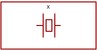
Crystal |
 |
LED |
 |
Light detecting diode |
 |
Volt bar
(power supply) |
 |
Chassis GND |
 |
Normally open switch |
 |
Normally closed switch |
 |
Switch SPDT |
Schematic symbols for active devices:
 |
NPN,PNP transistior
|
 |
FET N,P channel |
 |
MOSFET N,P channel
|
 |
Darlington |
 |
Thyristor |
 |
Triac |
 |
Xenon tube |
Jump from schematic symbols to
Best Microcontroller Projects Home page.
Site Map | Terms of Use


Comments
Have your say about what you just read! Leave me a comment in the box below.
Don’t see the comments box? Log in to your Facebook account, give Facebook consent, then return to this page and refresh it.