- Home
- PIC Projects
- Servo Controller
12F675 Tutorial 7: A Servo controller driving a standard servo motor using serial port commands.
You can use this servo controller code to control a servo motor via the serial RS232 interface.
This servo controller generates a signals to control a standard servo motor (I used a Futaba servo but you can use any servo) using the 12F675 microcontroller. You can type a text command into a serial terminal e.g Hyperterminal to set the position of the servo.
The project software works slightly differently to the previous one as
interrupts are used for pulse timing - this lets it both service the serial
port input and generate the correctly timed servo pulse.
| Serial command | Pulse width | Servo motor position |
| s100<Return key> | 1.0ms | +45º(clockwise rotation) |
| s150<Return key> | 1.5ms | zero º position |
| s200<Return key> | 2.0ms | -45º(anti clockwise) |
Note: The software limits the maximum values to
1.0ms and 2.0ms but you can change this in the software if you need
to.
Solderless breadboard
The project uses
the same solderless breadboard as before but adds in a link from the serial
port connector to the MAX232 transceiver (for receiving serial data) and a 1k
resistor.

Learn about the tool used for creating
this diagram.
Circuit diagram
Again the timing source is provided by the internal 4MHz clock.

12F675 pinouts

Other views:
 |
 |
Servo controller Software
To get the file software project files and c source code click here.
ServoController Software
operation
Accurate timed pulses are generated using Timer 1 interrupts. For this project Timer 1 is enabled after Timer 0 triggers.
When Timer 0 triggers it enables the Timer 1 interrupt and just before this sets the Timer 1 overflow so that the Timer 1 interrupt will occur at an exact time from the triggering of Timer 0.
Also when Timer 0 triggers the servo pin is set high and when Timer 1 triggers the servo pin is set low. In this way an exact output pulse is generated to control the servo motor.
Note: This project does nothing until you type in commands - it does continuously generate the servo position signal but this is only changed from the zero position when a new command is accepted.
Servo Controller : Timer 0
The settings for
Timer 0 are exactly the same as those used in Tutorial 6.
Servo Controller : Multitasking
The most
interesting part of the servo controller software is that it is doing two
things at once - it uses a simple multitasking method that is suitable for use
in a memory constrained device e.g. 12F675.
The software
services two processes at once:
- Serial port input monitoring.
- Servo motor output.
For more general
information on multitasking click here.
As this is not a true multitasking system in which portions of time are
allocated to each process you need to carefully decide what the highest
priority tasks and lowest priority tasks are before coding starts.
For the servo controller it is easy; the servo motor has to have the highest
priority as the servo motor must be kept at the correct position regardless of
any other process. So you put this task directly into the interrupt service
routine (ISR).
Serial port reading is assigned as a lower priority task.
The three factors that allow the scheme to operate are:
- The interrupt is only going at 20ms (fairly slow).
- The serial port speed is 2400Baud (fairly slow).
- The interrupt
code is the minimum possible.
For (1); The
fact that the interrupt is slow means that any other code is interrupted
infrequently so that other code can get on with its job.
For (2); The fact that serial reading is slow means that the code is
insensitive to interrupts. Any interrupt will affect it slightly but the
slower this code has to go the better since the timing of the baud rate will be
less affected.
For (3); Any interrupt that does occur takes as little time as possible.
Note that all of this is a trade off. As
the interrupt rate/execution time is increased the lower priority tasks receive
less processing
timeand therefore it is important that the ISR is small so that it
has minimal impact on the lower priority code.
For more information on interrupts click here.
| //////////////////////////////////////////////////////////////////////// // Start here // void main() { U8 i,chr ; // general purpose loop var. U16 count=0 ; // restart duty - counter. U32 timeC=0 ; // use for time delays. char op[5]; init_ports(); init(); Soft_USART_Init(2400); enable_interrupts(); while(1) { check_serial_rx(); } } |
You can see that
the servo controller main loop code is trivial and basically if whizzes around
the infinite loop doing the check_serial_rx() action. This checks if the
input serial data line is low and if it is starts a serial receive action.
After a serial byte is received and decoded check_serial_rx() feeds
the data into the decode_input() routine.
The decode_input() routine takes each data byte
and inserts it into a buffer and when it receives a carriage return
character
(\r or the Enter key on the keyboard) it processes the data gathered so
far. The only command it accepts is s<nnn> where nnn must be 3
digits long.
The string_to_num() routine converts
the three digits into an unsigned int for use in the interrupt routine to set
the servo position.
Servo Controller : Interrupt Service Routine (ISR)
| //////////////////////////////////////////////////////////////////////// void interrupt(void) { unsigned int val; /////////////////////////////////////////////// // Timer 0 if (INTCON & (1<<T0IF) ) { // T0 overflowed ? INTCON &= ~(1<<T0IF); // clear timer0 overflow bit. // Fosc/4 x (Prescale) x (count to overflow) = repeat rate. // 1us x 128 x 156 = 20ms repeat rate. TMR0 = 256-156+2; // need 156 but looses TMR0 looses 2 time++; // Count 20ms periods for general use. // Now set up timer1 as a 1 shot timer // Set overflow for Timer 1 val = 65535-servoVal; // Use these vars for reporting debug st_TMR1L = val & 0x00ff; st_TMR1H = (val & 0xff00)>>8; TMR1H = st_TMR1H; // set high 1st so does not overflow immediately TMR1L = st_TMR1L; st_val = val; // Enable Timer 1.- every Timer 0 interrupt or 20ms = 1 shot. PIE1 |= (1<<TMR1IE); GPIO |= (1<<SERVO_BIT); // Set Servo on } /////////////////////////////////////////////// // Timer 1 if (PIR1 & (1<<TMR1IF) ) { PIR1 &= ~(1<<TMR1IF); // Clear flag. GPIO &= ~(1<<SERVO_BIT); // Reset servo } INTCON |= (1<<T0IE); // Enable Timer 0. // Note GIE set by RETFIE instruction (see assembler output). } |
Sections
highlighted in white above show you the one-shot use of Timer 1.
Timer 0 interrupt code
- val is set to overflow Timer1 after the servoVal period.
- Timer 1 is enabled.
- Servo output
is set high.
Timer 1
interrupt code
- Servo output is set low.
- Timer 1 is not re-enabled.
Servo Controller : Accuracy
This is exactly
the same as for Tutorial 6.
A secret : Controlling the servo controller
I would like to
show you an amazing programming tool - in fact if you have already downloaded
the source code I have included a file that uses this tool.
This tool is in fact a programming language and not just any language it is a
powerful gui generator but it goes way
beyond a gui tool. You can use it for just about any task you want (on the
PC) - and it is much much easier than using C to do a task.
To use the script included in the source files you need to download the tcl
program itself (that executes the tcl script) from
http://www.tcl.tk/
Once installed just double click the .tcl file in explorer. This will open
the program creating a gui and simple buttons to communicate with the servo
motor. Move the slider to control the servo!
Note: You can use TCL in many environments
including Windows, Linux, Mac - and with virtually no changes to the source
code - it is a multi platform language.
The servo-controller.tcl script 150 lines of code and is the basis of a servo
motor tester. If you did this in 'normal C' you would have to learn about a
million different things e.g. template libraries, memory allocation, file
pointers and many more and if you did this in C it would take 1500 lines of
code!!
Here is a screen shot of the servo controller script in action:
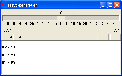
It is not polished - just functional -
but it only took a couple of hours to make and debug. If you want to you can
create menus, graphics, buttons - all the standard windows things. It also
has extensions for audio, object orientation, images etc
and it has no restrictions on use.
Note: that to create the text box (object
at bottom known as a widget) all you need is these two lines of code:
# View serial
data
text .t -width 20 -height
4
pack .t -side bottom -fill both -expand 1 -before .s1
Note: This text box has full editing
capability - you can add scrollbars using other widgets.
I just find that amazing and did you notice there is no compiler in sight - if
you want to change the script just load it into a text editor change it and
start it again - you won't have to wait ages for the code to compile - its
compiled on the fly by a byte code compiler inside the TCL engine.
The lower text box shows data coming back from the 12F675 servo controller
(IP->s150) The text s150 is made up from characters echoed back from the
12F675. The TCL script sends s150 at regular intervals.
If you move the top slider to the angle you want the output data is changed so
you can control the servo through this interface.
| Back | 12F675 Tutorial Index | Next |
Site Map | Terms of Use
Search:
Recent Articles
-
Arduino Float to String: Find out how to do it Easily!
 Arduino Float to String: Is there a simple function that does this for you? What is the one thing you must do to ensure your program is reliable?: Find out here.
 -
Arduino light sensor: A beginner's tutorial on DIY light sensing
 A beginners Arduino light sensor tutorial showing you how to use an LDR (Light Dependent Resitor) for live light sensing on the serial monitor
 -
Arduino Capacitive Sensor: Single Pin Touch Sensing
 Arduino Capacitive Sensor: Using Internal Hardware with no extra components, for touch sensing. Whaaaatttt?... How is this Magic performed?
 -
Privacy Policy
The privacy policy for this site. -
Arduino ADC: Everything you Must Know about the Built-In ADC
 How does the Arduino ADC work? Should you use 1023 or 1024 in your calculation? Find out the sample rate and how to use the voltage reference.
 -
Arduino ISP: Recover Dead Arduinos using a Free ISP.
 Arduino ISP: Easily burn the bootloader back into an Arduino with an ISP programmer. Don't buy an ISP programmer; use another Arduino as a Free ISP.
you so so so much
for all the information
you have provided in
your site it's
SUPERB and FANTASTIC."
- Ranish Pottath
the best and my favorite.
I find here many useful
projects and tips."
- Milan
bursach<at>gmail.com<
very, very easy and nice
to navigate!"
- Matt
matt_tr<at>
wolf359.cjb.net
"I am a newbie to PIC
and I wanted to say
how great your
site has been for me."
- Dave
de_scott<at>bellsouth.net
and perfect work.
congratulations."
- Suresh
integratredinfosys<at>
yahoo.com
words to define
yourweb site.
Very useful, uncovered,
honest and clear.
Thanks so much for
your time and works.
Regards."
- Anon
Comments
Have your say about what you just read! Leave me a comment in the box below.
Don’t see the comments box? Log in to your Facebook account, give Facebook consent, then return to this page and refresh it.