- Home
- Arduino Interfaces
- Arduino Joystick
Arduino Joystick: A Tutorial showing you exactly how to read the
outputs to get the precise position of the joystick. How to test the
joystick with a new library that makes it Easy.
This Arduino Joystick tutorial will show you how to connect an 2 axis
joystick to using any two Arduino analogue inputs. The joystick has two potentiometers one for vertical movement and
one for horizontal movement.
All that happens is that you put 5V at one end of the potentiometer and 0V at the
other end of the potentiometer, and the wiper adopts a value in between these
voltages. Then all you do is read the analogue values using an Arduino using the Arduino adc.
You can buy an Arduino joystick module as shown below - these have
the power pins and two analogue outputs, but the also have a push
button pin that activates when you push the joystick down.
For this Arduino joystick the potentiometer values are 4.4kOhm, others are usually 10k Ohms.
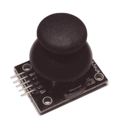
This
picture shows the physical structure of the Arduino joystick - two
potentiometers to top and right with the control stick in the middle.

Note: Of course whether VRx is horizontal and VRy is vertical depends on the orientation of the module. That won't really matter so change it in software as needed.
Arduino Joystick Sketch
The following sketch does not require a library and just
reads and displays the values from analogue input A0 and A1. It also
displays the button push output.
const int VRyPin = A1;
const int SWPin  = 5;

int VRx = 0;        // value read from the horizontal pot
int VRy = 0;        // value read from the vertical pot
int SW = 0;         // value read from the switch

void setup() {
  Serial.begin(9600);
  pinMode(SWPin,INPUT_PULLUP);
}

void loop() {

  VRx = analogRead(VRxPin);
  VRy = analogRead(VRyPin);
  SW = digitalRead(SWPin);

  // print the results to the Serial Monitor:
  Serial.print("VRrx = ");
  Serial.print(VRx);
  Serial.print("\tVRry = ");
  Serial.print(VRy);
  Serial.print("\tSW = ");
  Serial.println(SW);

  delay(200);
}
[File:joystick.ino]
joystick in the middle - output
Notice how the value is not exactly the center of the ADC vange (511) and that both are different values even though they represent the middle point.
VRrx = 524 VRry = 506 SW = 1
VRrx = 523 VRry = 506 SW = 1
VRrx = 524 VRry = 506 SW = 0
VRrx = 523 VRry = 506 SW = 0
VRrx = 523 VRry = 506 SW = 0
VRrx = 522 VRry = 505 SW = 1
VRrx = 523 VRry = 505 SW = 1
VRrx = 523 VRry = 505 SW = 1
VRrx = 524 VRry = 506 SW = 1
Joystick moved to limits - output
VRrx = 523 VRry = 506 SW = 1
VRrx = 512 VRry = 506 SW = 1
VRrx = 420 VRry = 506 SW = 1
VRrx = 218 VRry = 506 SW = 1
VRrx = 60 VRry = 506 SW = 1
VRrx = 0 VRry = 506 SW = 1
VRrx = 0 VRry = 506 SW = 1
VRrx = 0 VRry = 506 SW = 1
VRrx = 0 VRry = 506 SW = 1
VRrx = 0 VRry = 506 SW = 1
VRrx = 0 VRry = 506 SW = 1
VRrx = 0 VRry = 506 SW = 1
VRrx = 0 VRry = 506 SW = 1
VRrx = 253 VRry = 506 SW = 1
VRrx = 523 VRry = 506 SW = 1
VRrx = 524 VRry = 506 SW = 1
VRrx = 523 VRry = 506 SW = 1
VRrx = 524 VRry = 506 SW = 1
VRrx = 524 VRry = 506 SW = 1
VRrx = 675 VRry = 506 SW = 1
VRrx = 911 VRry = 506 SW = 1
VRrx = 1023 VRry = 506 SW = 1
VRrx = 1023 VRry = 507 SW = 1
VRrx = 1022 VRry = 506 SW = 1
VRrx = 1023 VRry = 507 SW = 1
VRrx = 1023 VRry = 506 SW = 1
VRrx = 1023 VRry = 506 SW = 1
VRrx = 1022 VRry = 506 SW = 1
VRrx = 523 VRry = 506 SW = 1
VRrx = 524 VRry = 505 SW = 1
VRrx = 523 VRry = 506 SW = 1
VRrx = 524 VRry = 505 SW = 1
VRrx = 523 VRry = 506 SW = 1
VRrx = 524 VRry = 373 SW = 1
VRrx = 523 VRry = 176 SW = 1
VRrx = 523 VRry = 0 SW = 1
VRrx = 523 VRry = 0 SW = 1
VRrx = 524 VRry = 0 SW = 1
VRrx = 524 VRry = 0 SW = 1
VRrx = 524 VRry = 0 SW = 1
VRrx = 523 VRry = 0 SW = 1
VRrx = 524 VRry = 0 SW = 1
VRrx = 524 VRry = 181 SW = 1
VRrx = 524 VRry = 320 SW = 1
VRrx = 523 VRry = 506 SW = 1
VRrx = 524 VRry = 506 SW = 1
VRrx = 523 VRry = 505 SW = 1
VRrx = 523 VRry = 505 SW = 1
VRrx = 523 VRry = 506 SW = 1
VRrx = 523 VRry = 522 SW = 1
VRrx = 523 VRry = 887 SW = 1
VRrx = 523 VRry = 1023 SW = 1
VRrx = 523 VRry = 1022 SW = 1
VRrx = 524 VRry = 1022 SW = 1
VRrx = 524 VRry = 1023 SW = 1
VRrx = 524 VRry = 1023 SW = 1
VRrx = 524 VRry = 1023 SW = 1
VRrx = 524 VRry = 506 SW = 1
The values show that the joystick returns to center values are the
same i.e. they are consistent but the values can be very different for each potentiometer.
Arduino Joystick Library
This library allows you to calibrate the Arduino Joystick and makes it easy to detect UP, DOWN,LEFT and RIGHT movements.
The parameters LOW HIGH and DIVITION determine how sensitive the code is to the values from the Arduino Joystick.
https://github.com/YuriiSalimov/AxisJoystick/blob/master/examples/SerialJoystick/SerialJoystick.ino
Download it from : Here
- Unzip the download.
- Change the folder name AxisJoystick-version to just AxisJoystick.
- Paste the modified folder on your Library folder (On your libraries folder inside Sketchbooks or Arduino software).
- Restart the IDE.
Commands in the library are:
singleRead()
multipleRead()
isPress()
isUp()
isDown()
isRight()
isLeft()
readVRx()
readVRy()
readSW()
calibrate(LOW, HIGH, DIVITION);
Instead of fiddling around with pins you can swap X and Y using:
XYReplacer(original) where original is the orignial object. Note include XYReplace.h - see example here.
Sketch - calibrating the joystick
/*
  Joystick axes calibration
  Reads a press of the calibrated joystick and displays information
  in the default Serial.
  https://github.com/YuriiSalimov/AxisJoystick
  Created by Yurii Salimov, January, 2019.
  Released into the public domain.
*/
 #define VRX_PIN A1
#define VRY_PIN A2
#define LOW_RANGE 0
#define HIGH_RANGE 1023
#define RANGE_DIVITION 100

Joystick* joystic;

// the setup function runs once when you press reset or power the board
void setup() {
  Serial.begin(9600);
  joystic = new AxisJoystick(SW_PIN, VRX_PIN, VRY_PIN);
  joystic->calibrate(LOW_RANGE, HIGH_RANGE, RANGE_DIVITION);
}

// the loop function runs over and over again forever
void loop() {
  Serial.print("| SingleRead: " + String(joystic->singleRead()));
  Serial.print(" | MultipleRead: " + String(joystic->multipleRead()));
  Serial.print(" | Press: " + String(joystic->isPress()));
  Serial.print(" | Up: " + String(joystic->isUp()));
  Serial.print(" | Down: " + String(joystic->isDown()));
  Serial.print(" | Right: " + String(joystic->isRight()));
  Serial.print(" | Left: " + String(joystic->isLeft()));
  Serial.print(" | VRx: " + String(joystic->readVRx()));
  Serial.print(" | VRy: " + String(joystic->readVRy()));
  Serial.println(" | SW: " + String(joystic->readSW()) + " |");
}
[File:example from github: ]
Range Mapping ADC values
Note If you want to map the output of the ADC to a different range of values then use the map function as follows:
outputValue = map(sensorValue, 0, 1023, 0, 255);
This will linearly map values with the minimum and maximum output:
0 maps to 0
and
1023 becomes 255.
Zero to 1023 becomes Zero to 255.
Note: See the 'arduino map' page to properly use the map function - there are some subtle problems there.
Site Map | Terms of Use
Search:
Recent Articles
-
Arduino Float to String: Find out how to do it Easily!
 Arduino Float to String: Is there a simple function that does this for you? What is the one thing you must do to ensure your program is reliable?: Find out here.
 -
Arduino light sensor: A beginner's tutorial on DIY light sensing
 A beginners Arduino light sensor tutorial showing you how to use an LDR (Light Dependent Resitor) for live light sensing on the serial monitor
 -
Arduino Capacitive Sensor: Single Pin Touch Sensing
 Arduino Capacitive Sensor: Using Internal Hardware with no extra components, for touch sensing. Whaaaatttt?... How is this Magic performed?
 -
Privacy Policy
The privacy policy for this site. -
Arduino ADC: Everything you Must Know about the Built-In ADC
 How does the Arduino ADC work? Should you use 1023 or 1024 in your calculation? Find out the sample rate and how to use the voltage reference.
 -
Arduino ISP: Recover Dead Arduinos using a Free ISP.
 Arduino ISP: Easily burn the bootloader back into an Arduino with an ISP programmer. Don't buy an ISP programmer; use another Arduino as a Free ISP.
you so so so much
for all the information
you have provided in
your site it's
SUPERB and FANTASTIC."
- Ranish Pottath
the best and my favorite.
I find here many useful
projects and tips."
- Milan
bursach<at>gmail.com<
very, very easy and nice
to navigate!"
- Matt
matt_tr<at>
wolf359.cjb.net
"I am a newbie to PIC
and I wanted to say
how great your
site has been for me."
- Dave
de_scott<at>bellsouth.net
and perfect work.
congratulations."
- Suresh
integratredinfosys<at>
yahoo.com
words to define
yourweb site.
Very useful, uncovered,
honest and clear.
Thanks so much for
your time and works.
Regards."
- Anon
Comments
Have your say about what you just read! Leave me a comment in the box below.
Don’t see the comments box? Log in to your Facebook account, give Facebook consent, then return to this page and refresh it.